PartsPlan
Manufacturer datasheet pages, tables, graphs and drawings for AI circuit design, cited by page.
Hosted MCP Server
npx add-mcp 'https://worker.partsplanai.com/mcp'Installs into Claude Code, Codex, Cursor and more
Documentation
PartsPlan is a hosted developer API (MCP server). Subscriptions pay for API usage. We are not a marketplace and don't sell parts or documents.
Your AI answers from the original datasheet
It finds the tables, graphs, drawings and conditions it needs in the manufacturer's original, and hands your AI the document and page number with them.
Free $0 · Personal $19/month plus applicable sales tax / VAT · Companies & organizations: by agreement — · 7M+ part numbers your AI can check through the API (as of October 2026)
Check the answer against page 6 of the original
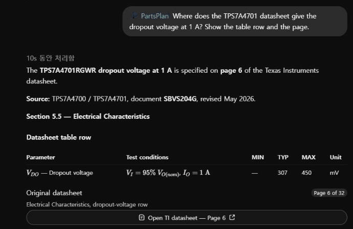
A real ChatGPT session using PartsPlan · recorded October 2026
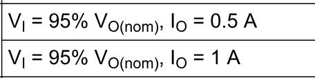
Datasheet original we checked it against Texas Instruments · TPS7A4700/TPS7A4701 (SBVS204G) · page 6
Q: Where is the TPS7A4701 dropout voltage at 1 A? → A: page 6 table, TYP 307 mV · MAX 450 mV
Connects to the AI you already use
What the AI built with PartsPlan
We gave the same AI the same tasks. These are what the side with PartsPlan connected actually produced.
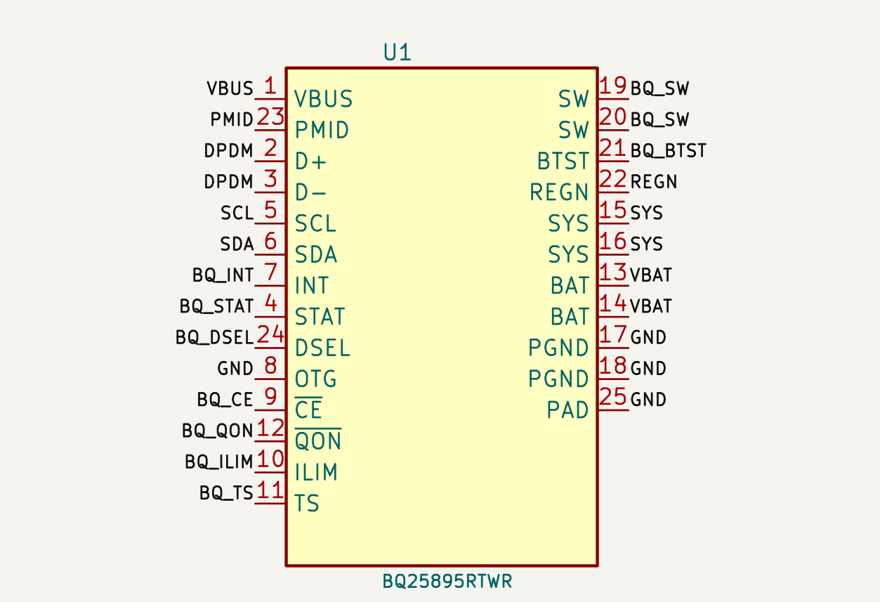
Charger IC schematic Part of the schematic the AI made in the test · every pin connected by a net label Major errors 0 vs 3 Without PartsPlan Same AI · same task · 90-minute cap · one run per side · the other side also used web, shell and KiCad · October 2026 Test output example — review before building
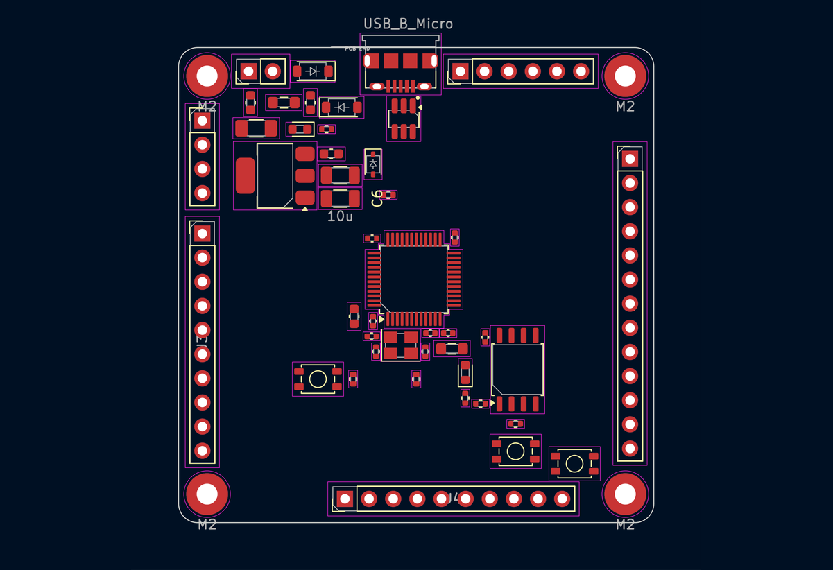
49-part STM32 board placement The board the AI placed in the test (KiCad 2D and 3D) · run 2 of 3 Average score (of 100, three-run average) 92.6 vs 81.7 Without PartsPlan Same AI · three runs per side, ahead in all three · the other side also used a shell and KiCad · October 2026

Buck and LDO two-layer board The board the AI routed in the test (KiCad 2D and 3D) · run 2 of 3 (20/20) Average time (three-run average) 10.6 min vs 21.3 min Without PartsPlan Quality score 19.7 vs 20.0 (of 20, three-run average) · same AI · the other side also used a shell and KiCad · October 2026 Test output example — review before building
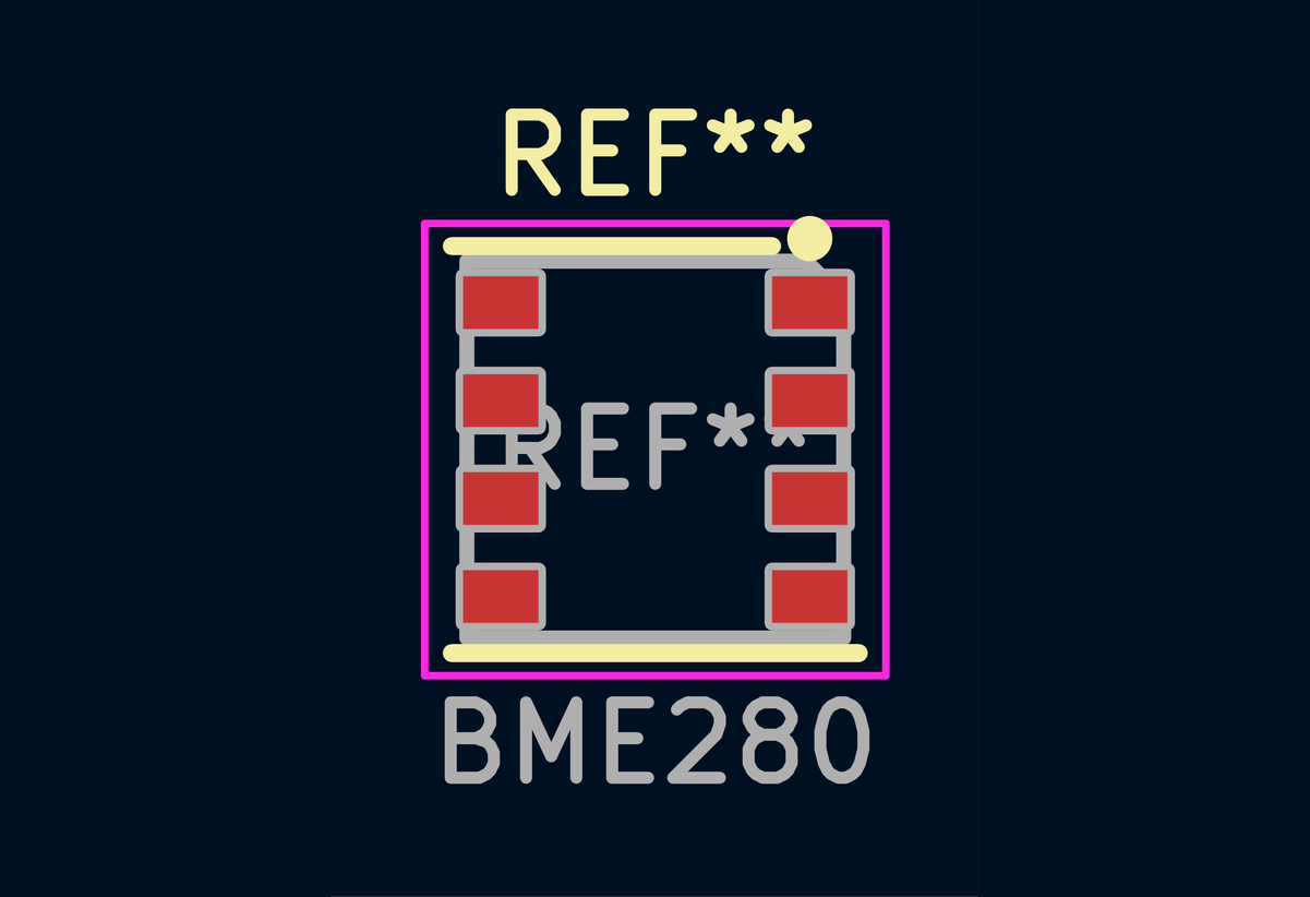
BME280 footprint The footprint the AI made in the test, in the KiCad footprint editor · run 1 of 3 Average time (three-run average) 10.1 min vs 24.8 min Without PartsPlan Six parts · same AI · three runs per side · the other side also used a shell and KiCad · October 2026 Test output example — review before building
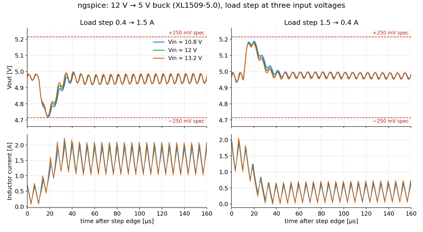
12 V→5 V buck load step An ngspice model the AI built from manufacturer datasheet values · values missing from the documents were stated as assumptions · shown: the re-run Time from schematic to simulation to PCB (first comparison, one run) 64 min vs 85 min Without PartsPlan Lesser-known Chinese and Taiwanese parts · all seven documents from the manufacturers · design quality on par · same AI · one run each · October 2026
With the EDA tools you use
- In the tests the AI produced schematics, boards and footprints in KiCad format, and those files open as they are in KiCad 10 (the images above are those files and placements drawn by KiCad).
- Package drawings and land patterns come exactly as printed, so whichever tool you draw in — EasyEDA, Altium or others — the evidence is the same original page.
Draw in EasyEDA, build with JLCPCB
Pass on the BOM exactly as EasyEDA exports it — design, datasheet checks and assembly ordering stay on the same part numbers.
- Design in EasyEDA Draw the circuit and export the BOM. The manufacturer column (for example MDD(辰达半导体)) comes out together with C numbers.
- Check with AI + PartsPlan Pass the BOM on as it is, and each line gets that maker's document — 14 of 14 lines of an actually exported BOM (October 2026, one run).
- Order assembly at JLCPCB The C numbers in an EasyEDA BOM are the same as JLCPCB assembly part numbers, so the checked part numbers go into the order as they are.
- Hand the AI the BOM exactly as EasyEDA exports it, and each line, passives included, is checked against that manufacturer's original datasheet — in a comparison test with the same AI (Claude) and a 14-line BOM in EasyEDA's format, lines confirmed from the manufacturer's original: web only 8, web + PartsPlan 14 (October 2026, one run).
- Each line comes back with the manufacturer's document and the pages to open first (pinout, package, electrical characteristics), and the AI opens those pages to review them.
- In a test with a BOM actually exported from EasyEDA Pro and passed on unedited — 14 lines, maker names as the export writes them (for example 'MDD(辰达半导体)', with the Chinese name alongside) and C numbers included — that maker's document was found for all 14 lines (October 2026, one run).
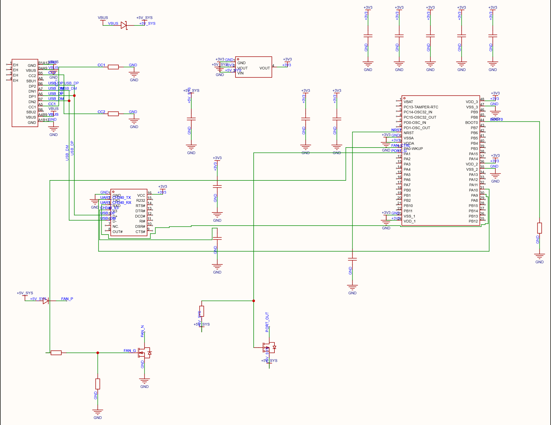
A comparison-test circuit made in EasyEDA Pro (25 parts). The 14-line BOM exported from this circuit was passed on unedited.
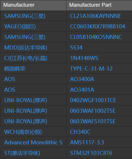
Captured directly in EasyEDA Pro: the test circuit's property list (the same parts as the 14-line BOM), with the manufacturer column exactly as EasyEDA writes it.
The originals your AI reads
Tables, graphs, circuits and package drawings exactly as the manufacturer printed them, with document and page number.
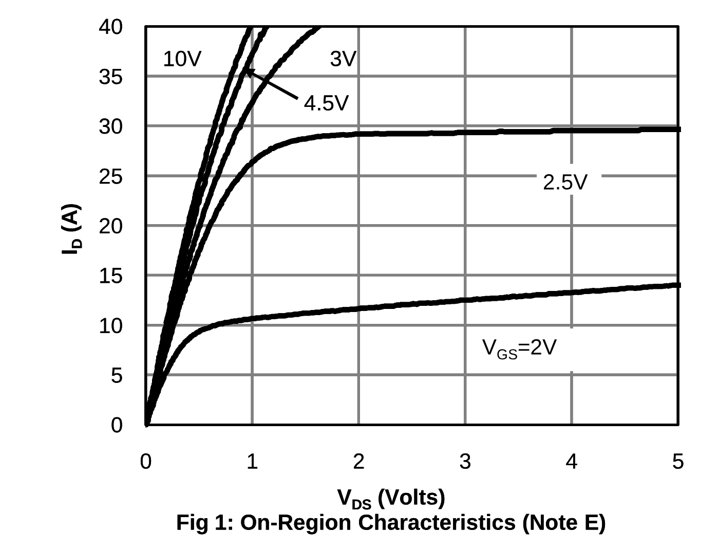
MOSFET output characteristics Alpha & Omega · AO3400A · page 3 · Fig 1 Enlarge Open the manufacturer's original ↗
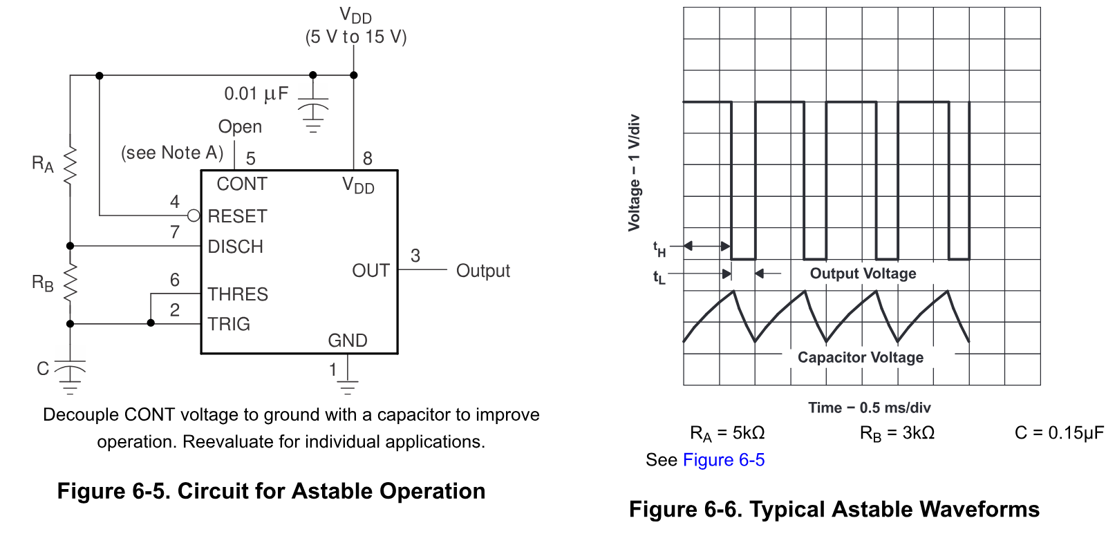
555 astable circuit and waveforms Texas Instruments · TLC555 · page 15 · Figures 6-5, 6-6 Enlarge Open the manufacturer's original ↗
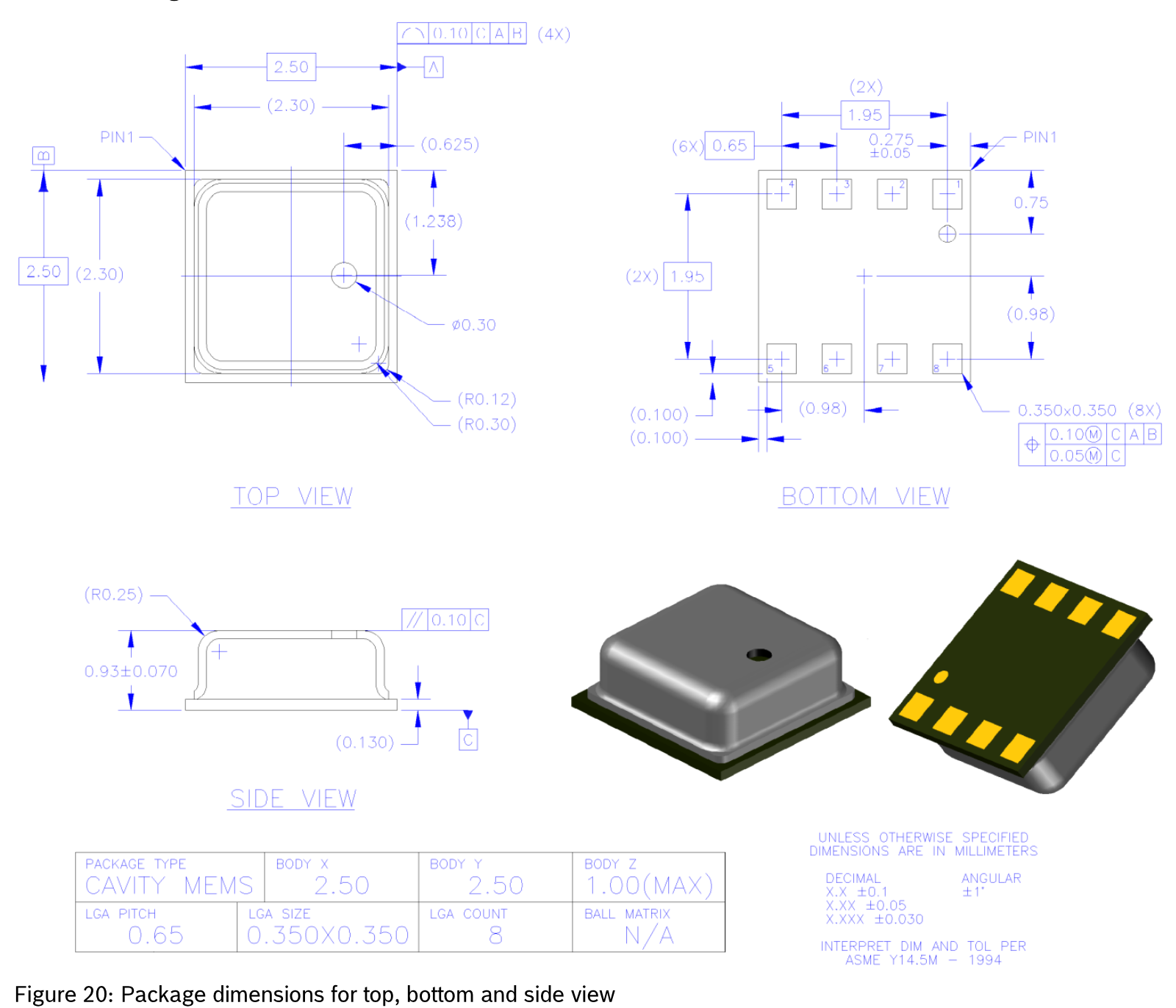
Package dimensions Bosch Sensortec · BME280 · page 42 · Figure 20 Enlarge Open the manufacturer's original ↗
Get started in three steps
- Create a free account (no card)
- Connect PartsPlan to your AI
- Ask about parts as you normally would
Try it on the parts you use
Start on the free plan and change plans whenever you need to.